SAMD21/SAMD51系列的快速参考
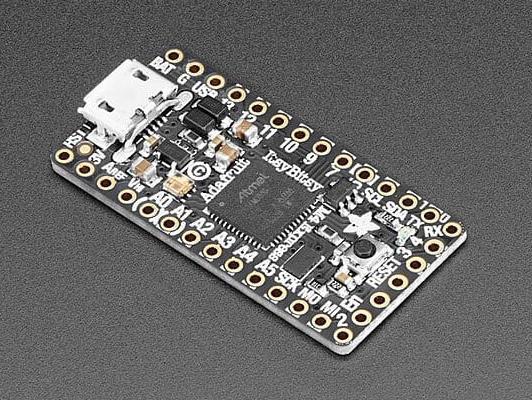
Adafruit ItsyBitsy M4 Express板。
以下是基于SAMD21/SAMD51的板的快速参考。如果这是您第一次使用此板,了解微控制器的概况可能会很有用:
安装MicroPython
参见教程的相应部分: SAMD上的MicroPython入门,它还包括故障排除小节。
通用板控制
MicroPython REPL位于USB端口上,配置为VCP模式。制表符补全有助于找出对象的方法。粘贴模式(Ctrl-E)用于将一大块Python代码粘贴到 REPL。
machine模块:
import machine

machine.freq()            # get the current frequency of the CPU
machine.freq(96_000_000)  # set the CPU frequency to 96 MHz
对于SAMD51,功能调用可接受的范围为1_000_000至200_000_0000(1 MHz至200 MHz),对于SAMD21,可接受的为1_000-0000至48_000_000(1 MHz到48 MHz)。根据数据表,SAMD51的安全范围为96 MHz至120 MHz。频率低于8 MHz时,USB将被禁用。频率低于48 MHz会影响UART、I2C和SPI的波特率。更改CPU频率后,必须再次设置这些值。ms和µs计时器不受频率变化的影响。
延迟和计时
使用 time模块:
import time

time.sleep(1)           # sleep for 1 second
time.sleep_ms(500)      # sleep for 500 milliseconds
time.sleep_us(10)       # sleep for 10 microseconds
start = time.ticks_ms() # get millisecond counter
delta = time.ticks_diff(time.ticks_ms(), start) # compute time difference
时钟和时间
时间信息提供了两组功能。所有板都有datetime()、mktime()和time()函数。带有32kHz晶体的电路板还提供了一个RTC()模块。纪元开始日期为2000年1月1日。
使用 time 模块:
import time

date_time = time.localtime()        # Show the actual date/time information
date_time = time.localtime(seconds) # decode the date/time form the seconds value
seconds = time.mktime(date_time_tuple) # Convert seconds to a datetime tuple
second = time.time()                # Return the actual system time.
date_time元组的格式遵循标准。date_time元组的µs值被忽略。在没有RTC模块的板上,时间。localtime(秒)设置系统时间。使用A模块:RTC模块:
from machine import RTC
rtc = RTC()
date_time = rtc.datetime()      # return the actual date & time.
rtc.datetime(date_time_tuple)   # Set date & time, ignoring weekday
date_time = rtc.now()           # Return date & time in Unix order.
rtc.calibration(value)          # Set a calibration factor
工作日值集将被忽略,并在返回的元组中从实际日期开始计算。rtc。now()仅在SAMD51板上提供。rtc中使用的值。calibration()调用的范围从-127到127。它大致定义了一个ppm的数量,时钟可以运行得更快或更慢。
Timers
SAMD21/SAMD51使用软件计时器machine.Timer类:
from machine import Timer

tim0 = Timer()
tim0.init(period=5000, mode=Timer.ONE_SHOT, callback=lambda t:print(0))

tim1 = Timer()
tim1.init(period=2000, mode=Timer.PERIODIC, callback=lambda t:print(1))
周期以毫秒为单位。
引脚和GPIO
使用 machine.Pin 类:
from machine import Pin

p0 = Pin('D0', Pin.OUT) # create output pin on GPIO0
p0.on()                 # set pin to "on" (high) level
p0.off()                # set pin to "off" (low) level
p0.value(1)             # set pin to on/high

p2 = Pin('D2', Pin.IN)  # create input pin on GPIO2
print(p2.value())       # get value, 0 or 1

p4 = Pin('D4', Pin.IN, Pin.PULL_UP) # enable internal pull-up resistor
p7 = Pin("PA07", Pin.OUT, value=1) # set pin high on creation
引脚可以用字符串或数字表示。字符串是相应板的引脚标签,如“D0”或“SDA”,或形式为“Pxnn”,其中x是A、B、C或D,nn是0-31范围内的两位数。例如:“PA03”、“PD31”。
引脚号是以下范围内的MCU端口号:
PA0..PA31:  0..31
PB0..PB31: 32..63
PC0..PC31: 64..95
PD0..PD31: 96..127
注:在Adafruit Feather和ItsyBity板上,引脚D5连接到外部门输出,因此只能用作输入。
UART(串行总线)
见 machine.UART.
# Use UART 3 on a ItsyBitsy M4 board
from machine import UART

uart3 = UART(3, tx=Pin(1), rx=Pin(0), baudrate=115200)
uart3.write('hello')  # write 5 bytes
uart3.read(5)         # read up to 5 bytes
SAMD21/SAMD51 MCU具有多达八个硬件,称为SERCOM设备,可以用作UART、SPI或I2C设备,但并非每个MCU变体和板都为用户提供所有TX和RX引脚。有关设备引脚和UART信号的分配,请参阅SAMD引脚.
PWM(脉宽调制)
SAMD21/SAMD51 MCU的多达五个定时器设备用于创建PWM信号。
PWM功能由 machine.PWM类提供。它支持为该类列出的所有基本方法。
# Samples for Adafruit ItsyBitsy M4 Express

from machine import Pin, PWM

pwm = PWM(Pin(7))      # create PWM object from a pin
pwm.freq()             # get current frequency
pwm.freq(1000)         # set frequency
pwm.duty_u16()         # get current duty cycle, range 0-65535
pwm.duty_u16(200)      # set duty cycle, range 0-65535
pwm.deinit()           # turn off PWM on the pin

pwm                    # show the PWM objects properties
PWM构造器
- class PWM(dest, freq, duty_u16, duty_ns, *, invert, device)
使用以下参数构造并返回新的PWM对象:
dest 是输出PWM的Pin对象。
PWM对象由TCC定时器模块提供。TCC定时器模块最多有六个通道和八个输出。模块的所有通道以相同的频率运行,但允许不同的占空比。输出以模n的方式分配给通道,其中n是通道的数量。通道的输出具有相同的频率和占空比,但可能具有不同的极性。例如,如果一个模块有四个通道,输出0和4、1和5、2和6、3和7共享相同的频率和占空比。
一次只能指定duty_u16和duty_ns中的一个。
关键字参数:
freq 应该是一个整数,该整数设置PWM周期的频率(Hz)。有效频率范围为1 Hz至24 MHz。
duty_u16将占空比设置为比率
duty_u16 / 65536。仅当未使用相应子模块的a和B通道时,才能更改X通道的占空比。否则,X通道的duty_16值为32768(50%)。duty_ns以纳秒为单位设置脉冲宽度。X通道的限制也适用。
invert=True|False。设置一个位会反转相应的输出。
device=n 使用TCC模块n(如果可用)。在某些针脚处,可以使用两个TCC模块。如果未提及设备,软件将尝试使用尚未用于PWM信号的模块。但是,如果引脚应具有相同的频率和/或占空比以同步改变,则它们必须由相同的TCC模块驱动。
PWM方法
这些方法与泛型machine.PWM类相同,init()方法具有额外的关键字参数,与构造函数的关键字参数匹配。
PWM引脚分配
以与Pin类相同的方式指定Pin。有关PWM信号的引脚分配,请参阅SAMD pinout。
ADC(模数转换)
在SAMD21/SAMD51上,标有“Ann”的引脚上提供ADC功能。
使用 machine.ADC类:
from machine import ADC

adc0 = ADC(Pin("A0"))            # create ADC object on ADC pin, average=16
adc0.read_u16()                  # read value, 0-65536 across voltage range 0.0v - 3.3v
adc1 = ADC(Pin("A1"), average=1) # create ADC object on ADC pin, average=1
ADC的分辨率是12位,精度为12位,与read_u16()返回的值无关。如果您需要更高的分辨率或更高的精度,请使用外部ADC。
ADC构造函数
- class ADC(dest, *, average=16)
使用以下参数构造并返回新的ADC对象:
dest是输出ADC的Pin对象。
关键字参数:
使用平均值来降低噪声。值为16时,LSB噪声约为1位数。
DAC(数模转换)
DAC类提供快速数模转换。用法示例:
from machine import DAC

dac0 = DAC(0)                    # create DAC object on DAC pin A0
dac0.write(1023)                 # write value, 0-4095 across voltage range 0.0v - 3.3v
dac1 = DAC(1)                    # create DAC object on DAC pin A1
dac1.write(2000)                 # write value, 0-4095 across voltage range 0.0v - 3.3v
SAMD51的DAC分辨率为12位,SAMD21的分辨率为10位。SAMD21设备在GPIO PA02处有1个DAC通道,SAMD51设备在GPIO PA02和PA05处有2个DAC通道。
软件SPI总线
软件SPI(使用位碰撞)在所有引脚上工作,并通过 machine.SoftSPI类访问。
from machine import Pin, SoftSPI

# construct a SoftSPI bus on the given pins
# polarity is the idle state of SCK
# phase=0 means sample on the first edge of SCK, phase=1 means the second
spi = SoftSPI(baudrate=100000, polarity=1, phase=0, sck=Pin(7), mosi=Pin(9), miso=Pin(10))

spi.init(baudrate=200000) # set the baud rate

spi.read(10)            # read 10 bytes on MISO
spi.read(10, 0xff)      # read 10 bytes while outputting 0xff on MOSI

buf = bytearray(50)     # create a buffer
spi.readinto(buf)       # read into the given buffer (reads 50 bytes in this case)
spi.readinto(buf, 0xff) # read into the given buffer and output 0xff on MOSI

spi.write(b'12345')     # write 5 bytes on MOSI

buf = bytearray(4)      # create a buffer
spi.write_readinto(b'1234', buf) # write to MOSI and read from MISO into the buffer
spi.write_readinto(buf, buf) # write buf to MOSI and read MISO back into buf
支持的最高波特率为500000。
硬件SPI总线
SAMD21/SAMD51 MCU具有多达八个硬件,称为SERCOM设备,可以用作UART、SPI或I2C设备,但并非每个MCU变体和板都为用户暴露所有信号引脚。硬件SPI通过machine.SPI类访问,其方法与上述软件SPI相同:
from machine import SPI

spi = SPI(1, sck=Pin("SCK"), mosi=Pin("MOSI"), miso=Pin("MISO"), baudrate=10000000)
spi.write('Hello World')
如果未指定味噌,则不使用味噌。有关SPI设备和信号的引脚分配,请参阅SAMD pinout。
注意:即使目前最高的可靠波特率约为24 Mhz,设置波特率也不一定会产生准确的频率,尤其是在高波特率时。
软件I2C总线
软件I2C(使用位碰撞)适用于所有支持输出的引脚,并通过 machine.SoftI2C 类访问:
from machine import Pin, SoftI2C

i2c = SoftI2C(scl=Pin(10), sda=Pin(11), freq=100000)

i2c.scan()              # scan for devices

i2c.readfrom(0x3a, 4)   # read 4 bytes from device with address 0x3a
i2c.writeto(0x3a, '12') # write '12' to device with address 0x3a

buf = bytearray(10)     # create a buffer with 10 bytes
i2c.writeto(0x3a, buf)  # write the given buffer to the slave
最高支持频率为400000。
硬件I2C总线
SAMD21/SAMD51 MCU具有多达八个硬件,称为SERCOM设备,可以用作UART、SPI或I2C设备,但并非每个MCU变体和板都为用户暴露所有信号引脚。有关设备引脚和I2C信号的分配,请参阅SAMD pinout。
硬件I2C通过 machine.I2C类访问,其方法与上述软件SPI相同:
from machine import I2C

i2c = I2C(2, scl=Pin("SCL"), sda=Pin("SDA"), freq=400_000)
i2c.writeto(0x76, b"Hello World")
OneWire驱动程序
OneWire驱动程序在软件中实现,适用于所有引脚:
from machine import Pin
import onewire

ow = onewire.OneWire(Pin(12)) # create a OneWire bus on GPIO12
ow.scan()                     # return a list of devices on the bus
ow.reset()                    # reset the bus
ow.readbyte()                 # read a byte
ow.writebyte(0x12)            # write a byte on the bus
ow.write('123')               # write bytes on the bus
ow.select_rom(b'12345678')    # select a specific device by its ROM code
DS18S20和DS18B20设备有一个特定的驱动程序:
import time, ds18x20
ds = ds18x20.DS18X20(ow)
roms = ds.scan()
ds.convert_temp()
time.sleep_ms(750)
for rom in roms:
    print(ds.read_temp(rom))
确保在数据线上放置4.7k上拉电阻器。请注意,每次要采样温度时都必须调用convert_temp()方法。
DHT驱动程序
DHT驱动程序在软件中实现,适用于所有引脚:
import dht
import machine

d = dht.DHT11(machine.Pin(4))
d.measure()
d.temperature() # eg. 23 (°C)
d.humidity()    # eg. 41 (% RH)

d = dht.DHT22(machine.Pin(4))
d.measure()
d.temperature() # eg. 23.6 (°C)
d.humidity()    # eg. 41.3 (% RH)
确保数据线上有一个4.7k的上拉电阻器。某些DHT模块可能已经有一个。
驱动APA102 LED
某些Adafruit板上的APA102可以使用SoftSPI进行控制:
from machine import SoftSPI, Pin
# create the SPI object. miso can be any unused pin.
spi=SoftSPI(sck=Pin(25), mosi=Pin(26), miso=Pin(14))

# define a little function that writes the data with
# preamble and postfix
def write(red, green, blue):
    spi.write(b"\x00\x00\x00\x00\xff")
    spi.write(bytearray((blue, green, red)))
    spi.write(b"\xff\xff\xff")

# set the LED to red
write(128, 0, 0)
由于SoftSPI不允许miso未定义,因此必须将miso分配给未使用的引脚。
驱动Neopixel LED
内置机器。bitstream()方法支持结合MicroPython驱动程序库中的Neopixel驱动程序驱动NeopixelLED:
import neopixel
import machine

# 1 LED connected to Pin D8 on Adafruit Feather boards
p = machine.Pin(8, machine.Pin.OUT)
n = neopixel.NeoPixel(p, 1)

# set the led to red.
n[0] = (128, 0, 0)

# Update the LED.
n.write()
machine.bitstream() 被设置为48MHz的SAMD21时钟频率和120MHz的SAMD51时钟频率。在其他时钟频率下,计时将不合适。
正在传输文件
文件可以传输到SAMD21/SAMD51设备,例如使用 mpremote工具。请参阅MicroPython论坛,了解社区支持的将文件传输到SAMD21/SAMD51板(如rshell或Thonny)的替代方案。