OpenMV Cam快速参考
通用硬件控制
See pyb.
import pyb

pyb.repl_uart(pyb.UART(3, 9600, timeout_char=1000)) # duplicate REPL on UART(3) 在UART(3)上重置REPL
pyb.wfi() # pause CPU, waiting for interrupt 暂停cpu,等待中断
pyb.stop() # stop CPU, waiting for external interrupt 停止cpu,等待外部中断
延时和时间
Use the time module:
import utime

time.sleep(1)           # sleep for 1 second 延时1s
time.sleep_ms(500)      # sleep for 500 milliseconds 延时500ms
time.sleep_us(10)       # sleep for 10 microseconds 延时10us
start = time.ticks_ms() # get value of millisecond counter  获取毫秒计数器的值
delta = time.ticks_diff(time.ticks_ms(), start) # compute time difference 计算时间差
LED 发光二极管
See pyb.LED.
from pyb import LED

led = LED(1) # 红色 led
led.toggle()
led.on()
led.off()
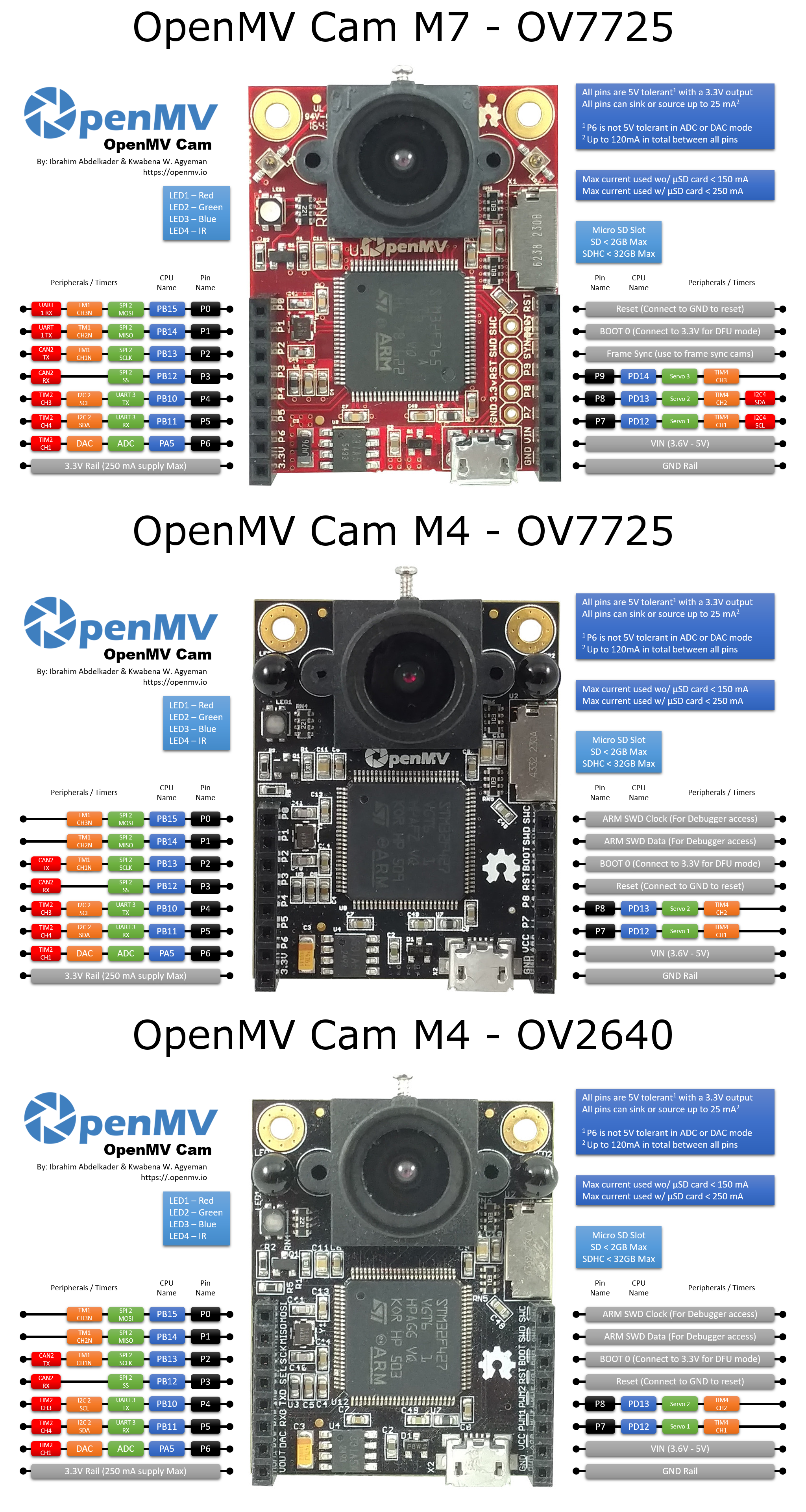
LED Pinout:
- LED(1) -> 红色 RGB LED Segment
- LED(2) -> 绿色 RGB LED Segment
- LED(3) -> 蓝色 RGB LED Segment
- LED(4) -> 红外 LEDs
引脚和GPIO
See pyb.Pin.
from pyb import Pin

p_out = Pin('P7', Pin.OUT_PP)
p_out.high()
p_out.low()

p_in = Pin('P8', Pin.IN, Pin.PULL_UP)
p_in.value() # get value, 0 or 1
GPIO引脚分配:
- Pin(‘P0’) -> P0 (PB15)
- Pin(‘P1’) -> P1 (PB14)
- Pin(‘P2’) -> P2 (PB13)
- Pin(‘P3’) -> P3 (PB12)
- Pin(‘P4’) -> P4 (PB10)
- Pin(‘P5’) -> P5 (PB11)
- Pin(‘P6’) -> P6 (PA5)
- Pin(‘P7’) -> P7 (PD12)
- Pin(‘P8’) -> P8 (PD13)
- Pin(‘P9’) -> P9 (PD14) (只在OpenMV Cam M7/H7)
所有引脚适配范围为5V,其输出为3V(在ADC或DAC模式下,P6的适配范围并不是5V)。
所有引脚最高输入或者输出25mA(所有引脚加起来最高120mA)。
舵机控制
见 pyb.Servo.
from pyb import Servo

s1 = Servo(1) # servo on position 1 (P7) 位置1的servo(P7)
s1.angle(45) # move to 45 degrees 移动到45度
s1.angle(-60, 1500) # move to -60 degrees in 1500ms 在1500ms内移动到-60度
s1.speed(50) # for continuous rotation servos 连续旋转舵机
Servo Pinout:
- Servo(1) -> P7 (PD12)
- Servo(2) -> P8 (PD13)
- Servo(3) -> P9 (PD14) (OpenMV Cam M7/H7 Only)
外部中断
See pyb.ExtInt.
from pyb import Pin, ExtInt

callback = lambda e: print("intr")
ext = ExtInt(Pin('P7'), ExtInt.IRQ_RISING, Pin.PULL_NONE, callback)
GPIO Pinout:
- Pin(‘P0’) -> P0 (PB15)
- Pin(‘P1’) -> P1 (PB14)
- Pin(‘P2’) -> P2 (PB13)
- Pin(‘P3’) -> P3 (PB12)
- Pin(‘P4’) -> P4 (PB10)
- Pin(‘P5’) -> P5 (PB11)
- Pin(‘P6’) -> P6 (PA5)
- Pin(‘P7’) -> P7 (PD12)
- Pin(‘P8’) -> P8 (PD13)
- Pin(‘P9’) -> P9 (PD14) (只在OpenMV Cam M7/H7)
定时器
See pyb.Timer.
from pyb import Timer

tim = Timer(4, freq=1000)
tim.counter() # get counter value 获取计时器值
tim.freq(0.5) # 0.5 Hz
tim.callback(lambda t: pyb.LED(1).toggle())
定时器引脚分配:
- Timer 1 Channel 3 Negative -> P0 (PB15)
- Timer 1 Channel 2 Negative -> P1 (PB14)
- Timer 1 Channel 1 Negative -> P2 (PB13)
- Timer 2 Channel 3 Positive -> P4 (PB10)
- Timer 2 Channel 4 Positive -> P5 (PB11)
- Timer 2 Channel 1 Positive -> P6 (PA5)
- Timer 4 Channel 1 Negative -> P7 (PD12)
- Timer 4 Channel 2 Negative -> P8 (PD13)
- Timer 4 Channel 3 Positive -> P9 (PD14) (OpenMV Cam M7/H7 Only)
PWM脉宽调制
from pyb import Pin, Timer

p = Pin('P7') # P7 has TIM4, CH1
tim = Timer(4, freq=1000)
ch = tim.channel(1, Timer.PWM, pin=p)
ch.pulse_width_percent(50)
定时器引脚分配:
- Timer 1 Channel 3 Negative -> P0 (PB15)
- Timer 1 Channel 2 Negative -> P1 (PB14)
- Timer 1 Channel 1 Negative -> P2 (PB13)
- Timer 2 Channel 3 Positive -> P4 (PB10)
- Timer 2 Channel 4 Positive -> P5 (PB11)
- Timer 2 Channel 1 Positive -> P6 (PA5)
- Timer 4 Channel 1 Negative -> P7 (PD12)
- Timer 4 Channel 2 Negative -> P8 (PD13)
- Timer 4 Channel 3 Positive -> P9 (PD14) (OpenMV Cam M7/H7 Only)
ADC (模数转换)
from pyb import Pin, ADC

adc = ADC(Pin('P6'))
adc.read() # read value, 0-4095 读取值,0-4095
ADC 引脚分配:
- ADC(Pin(‘P6’)) -> P6 (PA5)
ADC模式下,P6的适配范围为3.3V,而不是5V!
DAC (数模转换)
from pyb import Pin, DAC

dac = DAC('P6')
dac.write(120) # 输出介于0-255
DAC 引脚分配:
- DAC(Pin(‘P6’)) -> P6 (PA5)
DAC模式下,P6的适配范围为3.3V,而不是5V!
UART (串行总线)
See pyb.UART.
from pyb import UART

uart = UART(3, 9600, timeout_char=1000)
uart.write('hello')
uart.read(5) # read up to 5 bytes 读取5个字节
UART Pinout:
- UART 3 RX -> P5 (PB11)
- UART 3 TX -> P4 (PB10)
- UART 1 RX -> P0 (PB15) (只在OpenMV Cam M7/H7)
- UART 1 TX -> P1 (PB14) (只在OpenMV Cam M7/H7)
SPI总线
见 pyb.SPI.
from pyb import SPI

spi = SPI(2, SPI.MASTER, baudrate=1000000, polarity=1, phase=0)
spi.send('hello')
spi.recv(5) # receive 5 bytes on the bus 在总线上接收5个字节
spi.send_recv('hello') # send a receive 5 bytes 发送5个字节
SPI 引脚分配:
- SPI 2 MOSI (Master-Out-Slave-In) -> P0 (PB15)
- SPI 2 MISO (Master-In-Slave-Out) -> P1 (PB14)
- SPI 2 SCLK (Serial Clock) -> P2 (PB13)
- SPI 2 SS (Serial Select) -> P3 (PB12)
I2C总线
See pyb.I2C.
from pyb import I2C

i2c = I2C(2, I2C.MASTER, baudrate=100000)
i2c.scan() # returns list of slave addresses 返回一个从属设备地址的列表
i2c.send('hello', 0x42) # send 5 bytes to slave with address 0x42 使用0x42地址向从属设备发送5个字节
i2c.recv(5, 0x42) # receive 5 bytes from slave 从从属设备上接收5个字节
i2c.mem_read(2, 0x42, 0x10) # read 2 bytes from slave 0x42, slave memory 0x10 从地址为0x42从属设备上接收2个字节,从属存储器为0x10
i2c.mem_write('xy', 0x42, 0x10) # write 2 bytes to slave 0x42, slave memory 0x10 向地址为0x42的从属设备写入2个字节,从属存储器为0x10
I2C 引脚分配:
- I2C 2 SCL (Serial Clock) -> P4 (PB10)
- I2C 2 SDA (Serial Data) -> P5 (PB11)
- I2C 4 SCL (Serial Clock) -> P7 (PD13) (OpenMV Cam M7/H7 Only)
- I2C 4 SDA (Serial Data) -> P8 (PD12) (OpenMV Cam M7/H7 Only)