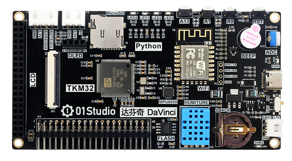
达芬奇 (TKM32F499) 快速参考手册
达芬奇开发板使用TKM32F499作为主控,以下是达芬奇图:
以下是快速参考内容,如果你是第一次使用达芬奇开发板,请考虑先阅读以下章节内容:
延时和时间
Use the time module:
import time

time.sleep(1)           # 睡眠1秒
time.sleep_ms(500)      # 睡眠500毫秒
time.sleep_us(10)       # 睡眠10微妙
start = time.ticks_ms() # 获取毫秒计时器开始值
delta = time.ticks_diff(time.ticks_ms(), start) # 计算从开始到当前时间的差值
定时器
TKM32F499拥有10个硬件定时器。使用 machine.Timer 类通过设置timer ID号为 1-10
from machine import Timer

tim0 = Timer(1)
tim0.init(period=5000, mode=Timer.ONE_SHOT, callback=lambda t:print(0))

tim1 = Timer(2)
tim1.init(period=2000, mode=Timer.PERIODIC, callback=lambda t:print(1))
该周期的单位为毫秒(ms), 暂时不支持虚拟定时器: id=-1.
引脚和GPIO口
使用 machine.Pin 模块:
from machine import Pin

p0 = Pin('C4', Pin.OUT)    # 创建对象p0,对应C4输出
p0.on()                 # 设置引脚为 "on" (1)高电平
p0.off()                # 设置引脚为 "off" (0)低电平
p0.value(1)             # 设置引脚为 "on" (1)高电平

p2 = Pin('A0', Pin.IN)     # 创建对象p2,对应A0口输入
print(p2.value())       # 获取引脚输入值, 0(低电平) 或者 1(高电平)

p4 = Pin('C6', Pin.IN, Pin.PULL_UP) # 打开内部上拉电阻
p5 = Pin('C7', Pin.OUT, value=1) # 初始化时候设置引脚的值为 1(高电平)
TKM32F499引脚使用与芯片引脚一致的命名方式,如PA0–>’A0’, PC4–>’C4’.详请参考其原理图。
ADC (模数转换)
TKM32F499一共有6路ADC,对应引脚为’ADC_4’,’ADC_5’,’B0’,’B1’,’B2’,’B3’. 请注意,ADC引脚上的输入电压必须 介于0.0v和3.3v之间(对应值为0-4095)。
Use the machine.ADC class:
from machine import ADC

adc = ADC('ADC_4')          # 在ADC_4引脚上创建ADC对象
adc.read_16()               # 读取测量值, 0-4095 表示电压从 0.0v - 3.3v
软件SPI总线
EPS32内部有两个SPI驱动。其中1个是通过软件实现 (bit-banging),并允许配置到所有引脚, 通过 machine.SoftSPI 类模块配置:
from machine import Pin, SoftSPI

# 在给定的引脚上创建SoftSPI总线
# (极性)polarity是指 SCK 空闲时候的状态
# (相位)phase=0 表示SCK在第1个边沿开始取样,phase=1 表示在第2个边沿开始。
spi = SoftSPI(baudrate=100000, polarity=1, phase=0, sck=Pin(0), mosi=Pin(2), miso=Pin(4))


spi.init(baudrate=200000) # 设置频率

spi.read(10)            # 在MISO引脚读取10字节数据
spi.read(10, 0xff)      # 在MISO引脚读取10字节数据同时在MOSI输出0xff

buf = bytearray(50)     # 建立缓冲区
spi.readinto(buf)       # 读取数据并存放在缓冲区 (这里读取50个字节)
spi.readinto(buf, 0xff) # 读取数据并存放在缓冲区,同时在MOSI输出0xff

spi.write(b'12345')     # 在MOSI引脚上写5字节数据

buf = bytearray(4)      # 建立缓冲区
spi.write_readinto(b'1234', buf) # 在MOSI引脚上写数据并将MISO读取数据存放到缓冲区
spi.write_readinto(buf, buf) # 在MOSI引脚上写缓冲区的数据并将MISO读取数据存放到缓冲区
Warning
目前在创建软件SPI对象时,sck, mosi 和 miso 所有 的引脚 必须 定义。
硬件SPI总线
有两个硬件SPI通道允许更高速率传输。 也可以配置成任意引脚,但相关引脚要 符合输入输出的方向性,这可以参阅(see 引脚和GPIO口)内容。通过自定义引脚而非 默认引脚,会降低传输速度,上限为40MHz。以下是硬件SPI总线默认引脚:
HSPI (id=1) |
VSPI (id=2) |
|
|---|---|---|
sck |
B2 |
A5 |
mosi |
B0 |
A7 |
miso |
B1 |
A6 |
Hardware SPI is accessed via the machine.SPI class and has the same methods as software SPI above:
from machine import Pin, SPI

hspi = SPI(1, 10000000)
vspi = SPI(2, baudrate=80000000, polarity=0, phase=0, bits=8, firstbit=0)
SoftI2C总线
I2C总线分软件和硬件对象,硬件可以定义0和1,通过配置可以在任意引脚上实现改功能, 详情请看 machine.SoftI2C 类模块:
from machine import Pin, SoftI2C

# 构建1个I2C对象
i2c = SoftI2C(scl=Pin(5), sda=Pin(4), freq=100000)

# 构建一个硬件 I2C 总线
i2c = I2C(0)
i2c = I2C(1, scl=Pin(5), sda=Pin(4), freq=400000)

i2c.scan()              # 扫描从设备

i2c.readfrom(0x3a, 4)   # 从地址为0x3a的从机设备读取4字节数据
i2c.writeto(0x3a, '12') # 向地址为0x3a的从机设备写入数据"12"

buf = bytearray(10)     # 创建1个10字节缓冲区
i2c.writeto(0x3a, buf)  # 写入缓冲区数据到从机
Hardware I2C bus
There are two hardware I2C peripherals with identifiers 0 and 1. Any available output-capable pins can be used for SCL and SDA but the defaults are given below.
I2C(1) |
I2C(3) |
|
|---|---|---|
scl |
B2 |
C1 |
sda |
B0 |
C0 |
The driver is accessed via the machine.I2C class and has the same methods as software I2C above:
from machine import Pin, I2C

i2c = I2C(0)
实时时钟(RTC)
See machine.RTC
from machine import RTC

rtc = RTC()
rtc.datetime((2017, 8, 23, 1, 12, 48, 0, 0)) # 设置时间(年,月,日,星期,时,分,秒,微秒)
                                             # 其中星期使用0-6表示星期一至星期日。
rtc.datetime() # 获取当前日期和时间
DHT 驱动
DHT 温湿度驱动允许通过软件在各个引脚上实现:
import dht
import machine

d = dht.DHT11(machine.Pin(4))
d.measure()
d.temperature() # eg. 23 (°C)
d.humidity()    # eg. 41 (% RH)

d = dht.DHT22(machine.Pin(4))
d.measure()
d.temperature() # eg. 23.6 (°C)
d.humidity()    # eg. 41.3 (% RH)
网络通讯(Network)
详情请参考 network.ESP8266
import network
    from machine import UART

uart = UART(1,115200)
wlan = network.ESP8266(uart) # 创建 station 接口
wlan.connect('essid', 'password') # 连接到指定WiFi网络
wlan.ifconfig()         # 获取接口的 IP/netmask(子网掩码)/gw(网关)/DNS 地址
一旦网络建立成功,你就可以通过 socket 模块创建和使用 TCP/UDP sockets 通讯,
以及通过 urequests 模块非常方便地发送 HTTP 请求。
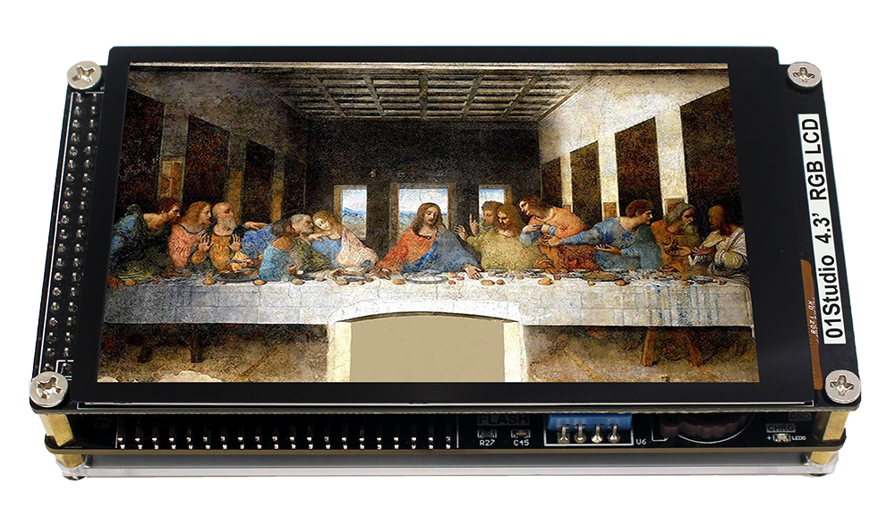
4.3寸RGB显示屏
详情请参考 tftlcd.LCD43R 和 touch.FT5436 .
LCD例程:
import tftlcd

d = tftlcd.LCD43R(portrait=1)  #构建LCD对象
d.fill((255, 255, 255))  #填充白色
d.drawRect(0, 0, 100, 100, (255,0,0))  #画红色矩形
d.printStr('Hello 01Studio!', 0, 0, (0,255,0))  #写字符
d.Picture(0, 0, '/flash/curry.jpg')  #显示图片
触摸例程:
import touch

t = touch.FT5436(portrait=1)  #构建触摸屏对象
t.read()  #获取触摸状态和坐标
7寸RGB显示屏
详情请参考 tftlcd.LCD7R 和 touch.GT911 .
LCD例程:
import tftlcd

d = tftlcd.LCD7R(portrait=1)  #构建LCD对象
d.fill((255, 255, 255))  #填充白色
d.drawRect(0, 0, 100, 100, (255,0,0))  #画红色矩形
d.printStr('Hello 01Studio!', 0, 0, (0,255,0))  #写字符
d.Picture(0, 0, '/flash/curry.jpg')  #显示图片
触摸例程:
import touch

t = touch.GT911(portrait=1)  #构建触摸屏对象
t.read()  #获取触摸状态和坐标
GUI-触摸按钮
TouchButton 类提供触摸按钮控制接口,通过构建该对象可以轻松显示屏触摸按钮应用。
详情请参考 gui.TouchButton .
示例:
import gui

B1 = gui.TouchButton(0,0,120,80,(255,0,0),'LED3',(255,255,255),fun1) #构建一个按钮
print(B1.ID())  #打印按钮编号