Lighting the LED
The lighting program is the first program to learn all the development boards. Just like learning all programming languages, learning the hello world is a sacred meaning.
1. Circuit diagram
It is well known that lighting an LED requires a power supply, a resistor, and an LED bulb. On the Dan Dock development board, there are three LEDs, the lines are as follows:
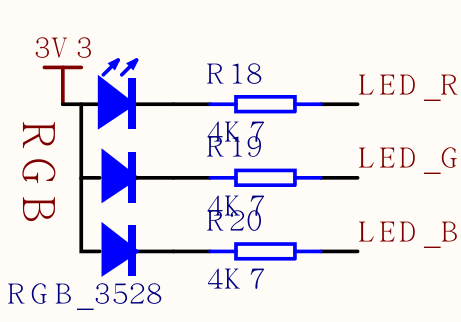
For example, we want to red light, i.e., LED_R connected to the LED, the LED can be seen in FIG positive 3.3V power supply has been connected, so long as we can LED_R LED lighting is low.
Note that
LED_Ris an alias for this pin, which is actually a pin connected to the chip, such as Pin13(13)
2. Config FPIOA(Field Programmable Input and Output Array)
Before writing the program, we need to know that the corresponding pins of the on-chip peripherals (such as GPIO, I2C, etc.) of the hardware K210 used by MaixPy can be arbitrarily set. The STM32 on-chip peripherals and pin correspondences have been fixed. Some of the pins can be multiplexed, compared to the K210 with greater degrees of freedom.
For example, I2C can use Pin11 and Pin12, or can be changed to any other pin.
3. Code
We control the LEDs and need to use GPIO
The procedure is as follows:
from Maix import GPIO

fm.register(board_info.LED_R, fm.fpioa.GPIO0)

led_r=GPIO(GPIO.GPIO0,GPIO.OUT)
led_r.value(0)
We only need to click the lines of the code one by one to the keyboard inside the terminal and press OK to execute.
Among them, we start with the package Maix introduced GPIO this class;
Front pin can be set K210, so we use .fm(fpioa manager) correspondence between peripherals and pin registration chip built-in object to this, here fm.fpioa.GPIO0 is a GPIO Peripheral K210's ( Note the difference between GPIO (peripheral) and pin (real hardware pin)), so the fm.fpioa.GPIO0 registration to pin board_info.LED_R;
Here board_info is a board type information can be entered in serial terminal board_info. then press TAB the button to see all the members, or just use pin number like 13.
Then define a GPIO subject, specific parameters to see GPIO the module's documentation, look in the left sidebar.
Use led_r.value(0) or led_r.value(1) to set high to low
It is already possible to light up here. If you know the Python syntax, you can try to write a for loop to achieve LED flashing~